 Yes, it has been forever since I've posted. No, in that time, I have done nothing on the Tinct. For that matter, I've done no electronics at all - the contents of my workbench are buried in boxes from when I moved, which was in July. Luckily, however, there are better people than me out there, and their work on the Tinct has continued. Unsped has some great shots of an OcTinct all cased up, and I hear Devon has been doing some great stuff at NYC Resistor.
As for me, well, since I can't foresee being able to get back into things in the near future, consider me dropped back off the face of the planet (to use unsped's words) once again. With any luck I'll post again one day.
Sunday, November 9, 2008
Better men than I (aka, Tinct Lives!)
Monday, March 24, 2008
Distinct Tincts
When I decided to go ahead and have my own PCBs made for what would become the Tinct I posted a request for people who would be willing to split the cost of fabrication with me. Two people - Brad Hill and Devon Jones - were brave (or foolish) enough to respond, despite having no reason to have any confidence that the design would work; without them, I probably wouldn't have proceeded because of cost. It's great having people with whom I can bounce ideas around, to whom I can complain when things aren't working, and to whom I can brag when things finally work.
I'm very pleased to report that, a mere week after I completed the first OcTinct, Devon has completed his. We decided to go with computer science-style numbering, so we're calling mine Tinct 0, and his is Tinct 1. Brad isn't slacking off, either, and has been working on a number of monome/Arduino crossover projects, which you can see pictures of on his Flickr page.
A few other quick Tinct updates: I'm pretty happy with the current version of the firmware, and have cleaned up and commented the code to make it usable by others. I'm willing to call this a "release candidate," whatever that means in this context. There are a few minor optimizations I want to try, but I have one that works without any known bugs. I rewrote the TinctSerial program; the serial performance of Processing sucked, so I rewrote it in Python (my first Python program ever). That solved all of my problems, although the current version is a processor hog. Devon taught me everything I know about Python (over IM, no less), so he's going to fix up the code. Finally, the controller board design is forthcoming. I just need to test my power supply circuitry to make sure it works, and then it's time to have the boards made. After that, all that's left to do is build a case!
Monday, March 17, 2008
The OcTinct is up and running!
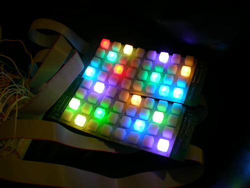
The OcTinct, the 8x8 member of the Tinct family (a full-colour monome clone), is up and running! The colours don't show up nearly as well in my videos (if anyone knows how to fix that, please let me know):
Technical details after the jump.
The Tinct is based off of custom-made PCBs and is being driven by an Arduino. The colour of each LED can be independently set, and the colour range is pretty much as close to "true" colour as you're going to get with an LED. The software is fully monome-compatible; the OSC command set is a superset of the monome protocol, adding in commands to control colour. Right now the colour control is pretty rudimentary, but will be expanded. There are two auxiliary analog inputs, which can be attached to anything that gives output as voltage: for example, potentiometers (as seen in the Life video above), or a two-axis accelerometer.
The controlling circuitry is currently all on breadboards, and is a horrible mess. You can see it in the videos. Eventually I'm going to make boards to hold this all nicely, and maybe tuck it into a nice case. Before I do that, I'm probably going to try a redesigned control scheme which uses two microcontrollers instead of one, in order to have a dedicated "video card." If it improves performance enough, I'll keep it that way. This is all about teaching myself electronics, though, so mostly I want to see if I can get the dual-processor scheme working.
Right now it's being powered off of the USB connection, but this is a temporary solution. I'm limiting the current to each 4x4 board via the transistors (I did this accidentally, but it worked out nicely for testing). What this means is that if any colour channel is trying to draw too much current (which occurs when more than 5 LEDs on a single panel are on at full blast in any of the three colour channels), then the colours might go a bit funny or dim. This will be fixed when I get around to building a proper power supply.
I have two extra sets of the custom boards for building this. If you're interested in trying to build one, get in touch (jmg *shift-2* upwardnotnorthward *dot* com).
Wednesday, March 5, 2008
RGB monome clone update and rename: Tinct!
The gist: the video above is of the second version of my RGB monome clone. The reason is looks so much worse that the first version on video is because it is so bright that it saturates my camera's CCD; in reality, it looks much better than the original. It is fully compatible with monome programs and the colour can be changed on the fly via software. The project has been renamed "Tinct," the 4x4 version shown above is called TiniTinct, and that's how I'll refer to them from now on. Right now, production kits are looking unlikely, but I do have a couple of extra sets of the prototype boards if anyone is interested in them. For more details continue after the jump.
As much as I like the name Trinome, I felt it implied a little too close an association with the real monome project. As a result, I was reluctant to actually use that name, and ended up just calling it "RGB monome clone" or "RGB button pad," which are boring. So, I've decided to rename the project Tinct. The 4x4 version shown above is the TiniTinct (pronounced Tiny Tinct), and the 8x8 version will be called the OcTinct. To be clear, the monome folks didn't ask me to make this change - they have been nothing but supportive - but I just decided to make it out of respect for them and their work.
As for the kit: thank you to everyone who has expressed interest. Right now, I just don't think it will happen. Making a kit would require another version of the 4x4 boards to fix small mistakes in the prototype (or designing an 8x8 version of the board), plus making a second board to hold controlling circuitry; this development would be expensive, and it's money I'm not willing to invest. There's also the issue of reliability and capabilities; this is very much a hacked-together project, and if I made it a kit, people would (reasonably) expect certain standards to be met. I'm just not sure I could be satisfied that I was meeting those standards without a lot more investment of time and money in this project. Finally, I just don't think I'm up to the task of providing technical support for a kit of this complexity. I'm finishing off a PhD, and I don't want to commit time to helping others build a kit. So, for the foreseeable future, a kit won't be produced. But, if you really are interested and up for it, there are a couple ways you can get your hands on this.
I have two extra sets (four boards each) of the prototype boards. When I put out the call earlier, I had two people respond, which made the production of these boards financially possible for me. They have their boards now and are working on duplicating my project. They were brave enough to buy the boards knowing that they might not work at all, or not as advertised. Well, now we know that you can at least use them to make a 4x4 monome-compatible device which can change colours on the fly. Soon I expect to have the 8x8 version up and running. A set of four bare boards will cost about $100. Parts will probably be another $100 or so (or much more, depending on the LEDs you get). If you understand and accept the difficulties involved and still want to duplicate my project (Don't say I didn't warn you!), please get in touch. If I hear from 8 people who want single boards before I hear from 2 people who want sets of four, then I'll be happy to sell the boards as single 4x4's. If I hear from enough people who are crazy enough to do this (let's say, six people looking for sets of four), then I'll order more of the prototype boards - on the understand that this is duplicating a prototype, not building a kit, and that minimal support will be provided. If you can't get it to work, don't come complaining to me!
The second way is if an "angel investor" were to appear (rather unlikely, I know). If someone were to pay me a lot of money, I would be willing to continue development on this. Cost would depend on the level of polish in the final product, but I think the least expensive I would do it for would be $1000, with prices rising from there depending on what exactly the demands of the project are. I don't expect this to happen, but I'm throwing it out there in case someone reading has both more money and more passion for this project than I do.
On to the technical details: I wrote my own version of monomeSerial in Processing to make it easier to hack during development. This software takes the OSC commands that the monome MSP patches and Chuck shreds send out, and translate them into serial commands that the Arduino can understand. It also receives the Serial data that the Arduino sends about button presses, and translates them into OSC commands that get sent back to the controlling program. I modified it slightly to create TinctSerial, which does the exact same thing, with the addition of an on-screen colour selector. You click on a colour in the window, and the Tinct changes its colour accordingly. The matching of colours isn't perfect yet, but you get a reasonable approximation of what you choose (and if anyone knows of a good way to accurately translate RGB values to the PWM frequencies needed to match that colour, please let me know!).
The LEDs are being driven by a single TLC5940 16-channel PWM driver. All 16 LEDs are connected to the chip simultaneously, and multiplexing is done over the colour channels. That means that only one colour channel is on at any given time, but it cycles through quickly enough that the eye can't see it. The camera, however, occasionally can, and so you might notice occasional "colour hiccups" in the video; these can't be seen in real life.
Switching from the digital pots to the TLC5940 has huge benefits: much brighter max brightness, and a colour resolution improved at least 20-fold. It does come with downsides, though. The main one is, the TLC5940 requires constant attention from the microprocessor. If too much time is spent doing something else, for example registering button presses, sending serial data, or interpreting received serial data, then the LEDs flicker visibly. Making sure that this doesn't happen has really been pushing my programming skills (which is great, because I always love a challenge). I've been able to get it running in monochrome mode without flickering, but I fear that frequently changing the colour of individual buttons might be impossible to do flicker-free in this setup. Of course, it all depends on your refresh speed. 30fps video might not be feasible, but 10fps might work; many full-colour applications that only require occasional colour changes should be fine. I think this problem could be overcome by using multiple microcontrollers, one to handle the buttons and serial I/O, and the other to take care of the TLC5940. Right now I'm not planning on taking the project in that direction (unless somebody offers me a lot of money to do it, which I doubt). If someone wants to buy my extra boards and give it a shot, you have my blessing.
The serial protocol I'm using is identical to the monome256 protocol, with the addition of the colour command. Since the monome protocol has message id's 0 and 1 reserved for messages coming from the device to the computer, I simply hijacked id 0 and use it to send colour data from the computer to the monome. I initially had some issues with commands getting misinterpreted. In particular, if you changed colours very rapidly you would sometimes get an LED turn on erroneously. This was a very annoying bug. I would think I had fixed it, test it and everything appeared fine, and then as soon as I started filming it it would pop up again. I kept trying to fix the problem in the firmware, but I finally tracked it down to a problem with the TinctSerial program and I believe I've fixed it; at the very least, the error rate is now low enough that I haven't been able to make it happen again. There were also timing issues on the receiving end: initially, the Life program was sending commands to the Tinct much too quickly, and so packets would get dropped. Another timing-related issue which was much more rare caused dropped packets, creating frameshift mutations (did I mention I'm working on my PhD in molecular biology?). These created completely unpredictable effects. I believe I've managed to quash all of these timing issues in firmware.
I caved and bought cheap Ebay RGB LEDs instead of the expensive superbrightleds.com ones. I couldn't help it, they're 1/5th the price! The quality isn't terrible: they are very bright and the colour is quite rich. The only problem is, the colours don't match from LED to LED like the superbrightleds.com ones do. Frankly, for the ~$80 I saved, I can live with it, but in a perfect world I'd use the superbrightleds.com ones.
Friday, February 29, 2008
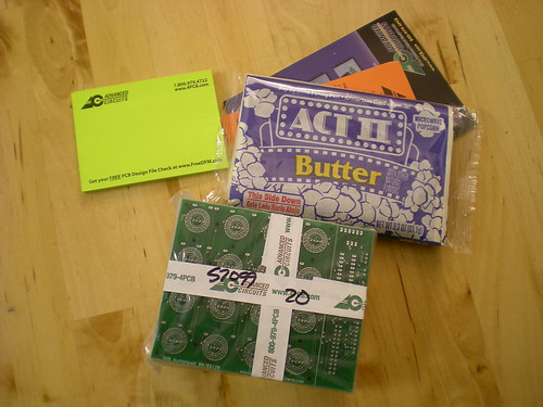
Boards have arrived!
Wednesday was board-day for me, as both my AVR ICSP breadboard adapter (ordered from BatchPCB) and my RGB button pad (ordered from Advanced Circuits) arrived. Much to my delight (and, to be honest, a little to my surprise), they both seem to work great. If you got in touch with me about the breadboard adapters, you'll be hearing from me soon; some are not spoken for, so if you'd like one, get in touch (jmg shift-2 upwardnotnorthward dot com). Expect a full post on the RGB pad once I've got it all up and running (right now I only have four RGB LEDs, so I'm waiting for more to arrive before I can fully build it).
Oh, and Advanced Circuits included a bag of microwave popcorn with my board order. Seriously.
Wednesday, February 13, 2008
In the works: RGB monome-esque kit
Update: This kit probably isn't going to happen for various reasons. Read about it in this post.
After talking with Brian, and obtaining his blessing (and advice), I've decided to invest the money to produce a custom PCB for an RGB button pad prototype. This design is completely different than my original, offering improved colour-depth and brightness: the pre-prototyping I've done blows the old one out of the water. I hope to have the design completed and the custom PCBs in-hand by the end of the month. What I'd like to do is order a medium-sized run of these boards so that I can split the development cost with like-minded hardware hackers. These would not be "plug and play" kits by any stretch of the imagination: these would require significant extra work to get them to do anything, and comfort working with electronics. The numbers will be kept small, so we can all easily communicate, and hence people who want to participate will need to be in touch with me first. This will be nothing like the monome kits, which are much more user friendly! You have been warned! If you fit this description, I need your feedback, so please read on and respond!
There are a few ways I could do this that I'm considering, each with their own advantages and disadvantages (both for me and for you). This would only be a board with the buttons and LEDs on it, as well as the circuitry to drive the LEDs. No logic would be on-board, that would have to be handled by an external microcontroller, most likely an Arduino (although your favourite board could work, too).
What I'm most likely to make first is a 4x4 button pad design to work with Sparkfun's buttons. It would include a small overhang to hold the circuitry to drive the LEDs, which would interface serially with whichever microcontroller platform you'd like. The serial interface would only control the LEDs; the buttons' wiring would be broken out to control however you like. All of the inputs and outputs will be neatly bundled together in a ribbon cable. Code and schematics for running it off of an Arduino (and possibly other platforms) would be made freely available. It would be possible to daisy-chain multiple 4x4 boards, but this would require more complicated off-board wiring. This kit would be the least expensive option, and also offers the most flexibility. The disadvantage would be that it would require the most outside wiring to get working, especially if you're planning on chaining multiple boards.
What I'd really like to make, personally, is an 8x8 button pad on a single baord, which would include a full serial interface for both the buttons and the LEDs, as well as power circuitry on-board (an 8x8 RGB pad uses a lot of current!). It is highly doubtful that I would do this initially for several reasons: for starters, it would be a much more complicated board for me to design and test. Perhaps more importantly, it would require me to invest in the professional edition of Eagle, which is an additional $600. That's money I need to put up initially, and it's money that would have to be factored into the cost of the boards for any other developers. So, unless feedback is overwhelmingly in favour of the 8x8 pad, this would most likely come later, if the interest existed.
Finally, there's the logic board. For now (and probably forever), this would be an Arduino. If you want to hook it up to something else, then by all means you could do so; if I hook it up to something else, I'll probably post code for it. For now, though, I'm developing on an Arduino and maybe AVR, so that's what I'll offer.
In terms of functionality, it will probably be possible to make this "monome-compatible," like my monomuino project. Of course, the colour functionality would not be accesible in this mode, you would have to pick the colour you wanted to display. I can't stress enough: if you want to build a monome, buy the kits from monome! This is for people interested in hardware tinkering. This device could also be controlled with a to-be-developed custom protocol which supports full colour, but in terms of software to utilize this, it would have to be custom written. Hopefully, if we get together a group of about a dozen people to do this, we'll be able to put together some neat stuff.
Here's what I'd like to hear from you:
- Which kit(s) would you be interested in? How many?
- The LEDs I like are from superbrightLEDs.com, and are much more expensive than ones you can find on Ebay, but much higher quality. If I bought a bulk order of those, and sold them at around cost (that's the discounted bulk cost, not the individual LED cost at superbrightLEDs), would you buy them bundled with the kit? (This would add ~$20 to a 4x4 kit, and ~$80 to an 8x8).
- Similarly, would you want the Sparkfun buttons bundled with the kit? This would save you shipping from Sparkfun.
- Can I contact you in the future with questions about the kit, and/or with announcements about the kits' availability?
- Any other questions or comments you might have
If you email me (at jmg -atsign- upwardnotnorthward -dot- com), I will not give your information out to anybody under any circumstances. I will contact you precisely once, to let you know that the boards are available, unless you explicitly give me permission to contact you more, or ask that I not contact you at all.
If you don't trust me with your email address, and never want to hear from me, then simply leave your thoughts in the comments below. That's cool, too.
If you don't trust me with your email address, and never want to hear from me, then simply leave your thoughts in the comments below. That's cool, too.
Monday, February 11, 2008
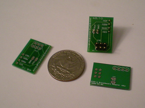
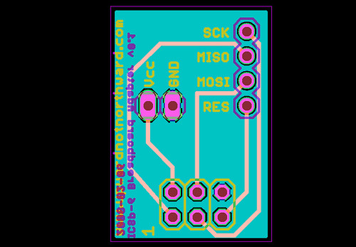
AVR ICSP 6-pin breadboard adapter
Update: the boards have arrived. If you're interested in getting one, please email me at jmg (shift-2) upwardnotnorthward (period) com.
I think I'm really starting to get the hang of EAGLE CAD; not only is it no longer frustrating, I now really enjoy designing boards in it.
I've been teaching myself about directly programming AVR chips (stay posted for an article on that), and since I'm too stubborn (and cheap) to pay for a development board, I built and have been using an Evil Mad Scientist Labs-style minimalist target board. It works great, but the problem is you more-or-less need a different board for every different type of chip you want to program, plus, you need to shuttle the chip back and forth from the breadboard to the programmer. It would be great to be able to program the chip in-breadboard, by the dual-row header pin won't allow that. You can run wires directly from your programmer to the breadboard, but that's a little messy. So, I decided to make a simple breadboard adapter for the ICSP header.
This has been done before, but I really don't like dealing with perfboard, and I was itching to try having a PCB manufactured, so I designed the adapter and ordered a bunch up from Sparkfun's BatchPCB service. My design is set up so that the Vcc and GND connect directly into the bus lines of the breadboard to save two wires later on. I ordered a bunch of extras, so if anyone out there is interested in one, drop me an email and we'll work something out (assuming they work properly when they arrive).
Tuesday, February 5, 2008
Announcing: Arduino serial communications class at The Hacktory!
I'm very pleased to announce that I will be teaching Advanced Physical Computing Experiments, a course about serial communications with Arduino, at The Hacktory in Philadelphia! The course is design as a natural follow-up to their highly successful introductory Arduino classes: whereas that class deals with how to set up the Arduino and use it to control simple components, this course will deal with controller more complicated, "smarter" components, as well as talking with other devices like computers.
I've mentioned before that one of the things that terrified me when I was starting out was the prospect of reading integrated circuit datasheets and figuring out how to interact with them. Now that I've gotten the hang of it, I'm amazed at the huge range of chips on the market, and how easy it is to interface with the vast majority of them once you know a few basics. It really has the potential to transform your projects, and I'm really excited about sharing this knowledge.
So what are you waiting for? Go sign up!
Monday, February 4, 2008
Brief updates: RGB monome-clone v0.2 status, learning Eagle, inspiration's lousy timing, etc.
A brief update for any subscribers I might have picked up:
As I mentioned in the original post, I've got a design in my head for a revised RGB button pad that will be much brighter and have a much wider range of colour. I'm going to need to design my own PCBs for it so I've been learning Eagle, because I can't get the open source KiCad running satisfactorily on OS X. It was tough at first, but Tod gave me some great advice that helped get my head in the right place:
I ordered 100 cheap common anode RGB LEDs from Ebay today. I figure if they're as good as the ones from superbrightleds.com then I've saved a tonne of money, and if they're not I can always get the more expensive ones once I'm done prototyping. A couple hours after ordering them I came up with a revised design that uses fewer components, less power, has a much simpler PCB, and, of course, requires common cathode LEDs. Just my luck. Still, I'm not positive which design will work better, so I'll probably just get some common cathodes as well and develop them both in parallel. Expect the first Rev. 2 write-up in the next week or two.
I'm expecting a shipment of components soon which should get me started on a lot of smaller things I've wanted to do for a while, which will also hopefully end up posted here. One of them is going to be a guide for transitioning from Arduino to AVR, using all open-source hardware and software. Hopefully this can help other people making the plunge as I am.
I've got a couple of other things in the works that I'm keeping under wraps for the time being. One of them should be announced in the next couple of days, and I'm very excited about it. The other is a new project, but I have no idea if it will work. I'm going to wait until I've got a working circuit before I post it, but if it does work, I think a lot of people will be interested in it. Keep watching the blog for updates.
As I mentioned in the original post, I've got a design in my head for a revised RGB button pad that will be much brighter and have a much wider range of colour. I'm going to need to design my own PCBs for it so I've been learning Eagle, because I can't get the open source KiCad running satisfactorily on OS X. It was tough at first, but Tod gave me some great advice that helped get my head in the right place:
One of the problems you'll encounter when first starting to use Eagle is that it may look like a GUI program, but you have to throw out anything people have learned about GUIs for the last 15 years.I also found Tangent's tutorials to be incredibly helpful, more-so than any written tutorial I found (the rest of his site is pretty great, too). Now that I'm getting the hang of it I'm really starting to love Eagle and have essentially decided it's worth the investment. I'm going to do a bit more breadboard prototyping before I buy the full version and design the PCB, so if any open-source evangelists want to switch me over to a free solution, you've got about a week to convince me!
I ordered 100 cheap common anode RGB LEDs from Ebay today. I figure if they're as good as the ones from superbrightleds.com then I've saved a tonne of money, and if they're not I can always get the more expensive ones once I'm done prototyping. A couple hours after ordering them I came up with a revised design that uses fewer components, less power, has a much simpler PCB, and, of course, requires common cathode LEDs. Just my luck. Still, I'm not positive which design will work better, so I'll probably just get some common cathodes as well and develop them both in parallel. Expect the first Rev. 2 write-up in the next week or two.
I'm expecting a shipment of components soon which should get me started on a lot of smaller things I've wanted to do for a while, which will also hopefully end up posted here. One of them is going to be a guide for transitioning from Arduino to AVR, using all open-source hardware and software. Hopefully this can help other people making the plunge as I am.
I've got a couple of other things in the works that I'm keeping under wraps for the time being. One of them should be announced in the next couple of days, and I'm very excited about it. The other is a new project, but I have no idea if it will work. I'm going to wait until I've got a working circuit before I post it, but if it does work, I think a lot of people will be interested in it. Keep watching the blog for updates.
Tuesday, January 29, 2008
monomuino: an Arduino-based monome compatible
I believe this is the first monome-compatible based on an Arduino (and possibly the first monome-compatible device, period). I call it the monomuino. I considered calling it a minimonome, since it is only 4x4, but I wanted to get some Arduino reference in there; as much fun as minimonomuino is to say, it's a bit of a mouthful. If I make a larger version, maybe I'll rename it. I'm pleased that, like the name of the original, there is a minimalist mathematical inspiration behind the term.
In an earlier post I presented a project that used the monome form-factor with the RGB colour blending in each button. That project, however, didn't communicate with a host computer, and had all of its software on the Arduino. This device uses the monome256 protocol to interact with MonomeSerial. The video above shows it pretending to be (one quadrant of) a monome sixty-four, interacting with several of the MaxMSP patches from the monome base collection. (Apologies as always for the lousy video quality!)
For information on how it works, read on.
For information on how it works, read on.
This project does not use the full RGB capabilities of my earlier button pad, because the monome protocol doesn't support it. Instead, I've connected the blue channels directly to the Arduino in a standard 4x4 multiplex arrangement, and the buttons as before. This uses essentially all of the pins on the Arduino to power just a 4x4 grid, so it obviously can't scale directly; I do believe, however, that with a couple of inexpensive chips added to it, I could scale up to an 8x8 or possibly higher.
The trickiest part of this project was getting MonomeSerial on OS X to recognize the Arduino as a monome (note that all of this information applies only on OS X; your mileage may vary on other systems). From what I can tell, MonomeSerial looks for a device named tty.usbserial-m40h-xxx, tty.usbserial-m64-xxxx, tty.usbserial-m128-xxx, or tty.usbserial-m256-xxx, where the first part indicates the device, and the x's are a (presumably unique) serial number. I tried making links to the Arduino device with the correct name format, but that didn't work; looking over the source for MonomeSerial, it appears to look for an event from the Kernel. I tried figuring out how to change the source to recognize other device names, but my C++ skills aren't up to snuff. So, I realize I had to change the serial number of my Arduino (or, more specifically, the serial number of the FT232 chip in my Arduino). If there's an easier way to do this, I'd love to hear about it in the comments!
To do this requires programming the chip's EEPROM. (Obligatory WARNING: if you kill your Arduino trying this, it's not my fault!) I found some Linux programs to do this (Google for FTDI EEPROM for others), but couldn't get any to compile on OS X, so, despite my distate for it, I grudgingly went to a Windows box. FTDI offers a utility called MProg for programming EEPROMs. Note that it requires the D2XX drivers, which I gather aren't the "normal" drivers that you already have installed if you're using an Arduino. MProg has one of those terribly unintuitive user-interfaces that only an extremely niche product can get away with (or maybe that's par for the course on Windows), but it got the job done. Soon enough, my Arduino was renamed tty.usbserial-m64-0001, and was recognized by MonomeSerial.
After that, implementation of the monome256 protocol was pretty straightforward. The only annoying part was figuring out what speed the serial connection was set to: I couldn't find it documented anywhere, so it was simply a matter of guessing and checking until something worked. I assumed it would be pretty fast, so I started at 115200 baud and worked my way down; since it turns out to be 9600 baud, it was a bit of an exercise in frustration. After seeing how frustrated it can be working with an extremely well-documented protocol, I have renewed respect for any hardware hackers who do real reverse-engineering! There were also some timing issues with my serial implementation, which were easily resolved by making sure I wasn't calling Serial.available() too often (not entirely sure why it was a problem, but it did the trick), and timing problems in the other direction, making sure I wasn't dropping any received commands.
So what's next? I see two obvious directions: one is to see if I can get an 8x8 pad running off the Arduino. As I said above, I'm fairly certain I can, but it would cost me another ~$100 or so in parts if I got them off the shelf, and I don't think I'm willing to invest that much in it. I'd much rather pursue my improved design for the RGB button pad. That requires designing my own PCB, which I've never done before, so it holds a lot more interest for me. The problem is that a 4x4 button pad PCB is larger than the free version of Eagle allows, and I haven't been able to get KiCad running satisfactorily on OS X (if anyone can help with that, it would be greatly appreciated!). The beta for version 5 of Eagle is a pretty huge improvement on OS X, though, so I might be willing to shell out once that's released.
Thanks to the great folks over at monome for making their hardware and software so open! Congratulations, too, on the amazing success of their most recent offering; these products are hard to get than Hannah Montana tickets!
As always, questions and comments are welcome and encouraged.
Sunday, January 27, 2008
Electronics shopping list, part II: Components
In part I I discussed the tools that one starting to play around with electronics should pick up - well, mostly I pointed out already existing lists of equipment, but who's counting. In this article I want to talk about the fun stuff: components.
One thing I wanted to get right off the bat was a big pile of parts, both so that I'd have a variety of things to play around with, and so that I wouldn't be missing any common parts when I needed to build something. I knew what various components did - resistors, capacitors, diodes, transistors - I just had no idea what values and types I would need and what I wouldn't. I was surprised at how little information I found on the subject, and that there didn't seem to be any good "starter packs" available (more on that later). I put together a list from this thread on the Arduino forums, along with Tom Igoe's books (Physical Computing and Making Things Talk, and a few other sources. Read on to see what I found.
One thing I wanted to get right off the bat was a big pile of parts, both so that I'd have a variety of things to play around with, and so that I wouldn't be missing any common parts when I needed to build something. I knew what various components did - resistors, capacitors, diodes, transistors - I just had no idea what values and types I would need and what I wouldn't. I was surprised at how little information I found on the subject, and that there didn't seem to be any good "starter packs" available (more on that later). I put together a list from this thread on the Arduino forums, along with Tom Igoe's books (Physical Computing and Making Things Talk, and a few other sources. Read on to see what I found.
A few preliminaries: I'm not going to go into too much explanation of how to use these components. That's best left for other articles, and besides, there's plenty of information out there (I highly recommend Lessons in Electric Circuits, a six volume set available free online in HTML or PDF format). I will, however, try to give enough information to understand what you're getting and why, and to link to relevant background information.
The values here assume you're working with microcontroller-level voltages (3.3V, 5V, and maybe occasionally 12V) and currents (less than 1A).
The list
This post ended up being much longer than I had anticipated, so here is a summary list of parts I recommend to start out with. For details, read on.
Generally I'm pointing out the cheapest options. Suggested quantities are in brackets. A few items are in italics, because they're less important. If anyone has any comments - good places to buy these things, alternatives, additions - please leave a comment at the bottom.
- Resistors:
- 1/4 W ceramic (get hundreds) - 22 Ohms, 47 Ohms, 100 Ohms, 220 Ohms, 470 Ohms, 1kOhms, 4.7kOhms, 10kOhms, 22kOhms, 100kOhms, and 1MOhms. (Other values if needed for specific projects)
- 1/4 W ceramic (get hundreds) - 22 Ohms, 47 Ohms, 100 Ohms, 220 Ohms, 470 Ohms, 1kOhms, 4.7kOhms, 10kOhms, 22kOhms, 100kOhms, and 1MOhms. (Other values if needed for specific projects)
- Capacitors:
- 50V ceramic (get dozens) - 22pF, 47pF, 100pF (0.1nF), and 100nF (0.1uF)
- 50V radial electrolytic (get dozens) - 1uF, 10uF, and 100uF
- 50V ceramic (get dozens) - 22pF, 47pF, 100pF (0.1nF), and 100nF (0.1uF)
- Diodes:
- General purpose (get dozens) - 1N4001, 1N4004 (1N400x will all probably be fine)
- Switching (get dozens) - 1N4148 or 1N914
- Zener (get 10-20) - 3.3V (I got 1N5226, but plenty of others will do), other voltages if you know you'll be dealing with them
- LEDs (get at least two dozen) - cheap red ones (and any others you might like)
- General purpose (get dozens) - 1N4001, 1N4004 (1N400x will all probably be fine)
- Transistors:
- General Purpose (get dozens) - 2N2222 (or PN2222, which is cheaper), 2N2907 (or PN2907)
- Power (a dozen, unless you plan on controlling high-voltage devices like motors; then use more) - TIP120
- General Purpose (get dozens) - 2N2222 (or PN2222, which is cheaper), 2N2907 (or PN2907)
- Integrated circuits:
- Be sure to get a DIP package (or anything ending in DIP, like PDIP) unless you want to do surface-mount soldering (if you're reading this, you probably don't). There are so many ICs, with so many functions, that it's impossible to make a good list. Any 74HC or 74LS are good to start, as are CD4xxx series, so find some that sound like fun. I recommend counters, multiplexers, BCD-to-seven segment decoders, and (slightly more advanced) shift registers as a good way to start to learn (get a couple each of several different types to play around with).
- Power supply (quantities depend on how many power-supply circuits you'll build):
- Again, be sure not to get surface mount packages; TO-220, TO-92, and TO-3 should all be safe
- Fixed - LM7805 5V 1A positive regulator (other voltages are LM78xx where xx is the voltage, if you know you need them); LM1084 3.3V 5A positive regulator
- Adjustable - LM317
- Breadboard power supply kit - not a necessity, but very convenient, plus a good way to practice your soldering
- Fixed - LM7805 5V 1A positive regulator (other voltages are LM78xx where xx is the voltage, if you know you need them); LM1084 3.3V 5A positive regulator
General advice on picking parts
Datasheets are scary at first; at least, they were to me. The best way to get over that is to read them, over and over again, and lots of them. There's a lot of information in them that you don't really need to worry about, so learn to pick out what's important. The main things you want to check are that the component you're looking at can handle the voltage, current, and power that you're going to be subjecting it to, so look for those numbers. If you don't know how to figure those out, then stop here and go read up on and power. You might want to check out Lessons in Electric Circuits, which is a fantastic free textbook to make sure you understand a little bit of the theory before you starting putting down cash.
Package deals
I looked around for package deals that included a wide variety of parts. Almost all that I encountered had two distinct problems: they included a lot of things that aren't really necessary (and not enough of things that are), and they are grossly overpriced. For example, Digi-key offers a kit with 365 resistors - 5 each of 73 different values - for $14.95. First of all, 5 of a given value really isn't enough; what if you have 8 LEDs that you want the same brightness? That aside, for $14.95, you should be able to buy at least 1495 resistors. You'd be much better off buying 100 each of 10 different values for $10 than getting that kit for $15.
While writing this entry I discovered Futurlec, an online store that seems to have very competitive prices. They offer several different value packs of different components, generally 100 pieces of various values, which appear to be a very good deal price-wise. The trade-off is that the values you get are unknown, and for that reason I wouldn't recommend making them the basis of your kit to begin with. I recommend stocking up on some key values, and then perhaps using these "mystery" packages to randomly fill in some gaps. In fact, I just placed an order for several of them in order to do just that.
Resistors
Resistors are essential for controlling how much current is flowing through a circuit, and as such you'll use them all the time. Fortunately, they are dirt cheap. The type you'll probably want as a beginner hobbyist are 1/4 Watt ceramic film (not ceramic composition, those are much more expensive). I was in Toronto over the holidays, where there are several good electronics stores, all of which sell resistors for a penny each, even in small quantities (I picked up about 1,500 of various values, 100-200 of each, so I won't have to worry about resistors for a long time). This is a rare occasion when brick-and-mortar stores seem to do better than online, unless you're buying in the thousands. The only online store I've seen with comparable prices for small quantities is Futurelec, whose resistor page is here. If you're buying in larger quantities, look around and see how well you can do.
All of the sources I found recommended resistor values of different orders of magnitude starting with 1.0, 2.2, and 4.7; I went with it and haven't had a problem yet. I got 100-200 each of 22, 47, 100, 220, 470, 1k, 4.7k, 10k, 22k, 100k, and 1M. The lowest order of magnitude is for limiting current in low-voltage situations (ie LEDs with high voltage drops), the mid range for most current limiting situations (normal LED series resistors, pin protection), and the high end for pull-up and pull-down resistors. The high end I've used the least, by far. Of course, other values come in handy, but these should do pretty well; remember that you can put resistors in series or parallel to get other values, too.
Capacitors
Capacitors are like tiny temporary batteries: they store energy up and then release it. The unit of capacitance is the farad (F), but one farad is pretty huge, so what you'll normally encounter are micro-, nano-, and picofarad ratings.
The most common use when dealing with microcontrollers seems to be to "de-noise" power lines; the idea is that the capacitor stores a little bit of charge, so if there are fluctuations from the power source, it can release or store charge to compensate for them. These are called bypass or decoupling capacitors, and some sources recommend using them constantly. I don't, and haven't encountered any problems yet, but it's something to think about when building your circuits.
There are many types of capacitors, but the only I've used so far are the cheapest and most common: ceramic (usually smaller values) and electrolytic (larger values). Generally speaking ceramic are non-polar (doesn't matter which way you put them in the circuit), while electrolytic are polar (there are positive and negative ends, so you need to be careful which way you put them in the circuit). Make sure the capacitors are rated for a voltage significantly higher than what you plan on using them in, just to be safe.
I picked up a wide range of values, but I've hardly had to use them at all. They're cheap (4 to 20 cents each), though, and a lot of circuits suggest them, so I'm glad to have them around. I have 22pF, 47pF, 100pF (0.1nF) and 100nF (0.1uF) ceramic capacitors, and 1uF, 10uF, and 100uF electrolytic capacitors. As in resistors, values starting with 2.2 and 4.7 seem to be popular; 22pF in particular crops up a lot, but I couldn't tell you what's special about that particular value.
Diodes (rectifiers)
Here's where things started getting a little trickier for me. Resistors and capacitors I had played with a lot in high school shop and physics class; I had played with them, knew equations that used them, and at least vaguely understood what the ratings and numbers meant. Diodes (also sometimes called rectifiers) were more of a mystery. I knew that they forced current to travel in only one direction, but I didn't have a good sense of when you need to use them, and what the various ratings in the datasheet meant. For that, I highly recommend Volume 3, Chapter 3 of the aforementioned Lessons in Electronic Circuits, particularly the section on diode ratings.
Many of the uses for diodes involve AC current, which I haven't dealt with at all and won't talk about. Briefly, some of the DC-related uses for diodes you might encounter are: as a snubber (also called a flyback diode), to protect circuits from stray current flow; for switching matrices, to prevent ghosting and masking (scroll down to section 8 on the linked page); and, using a Zener diode, to regulate a voltage drop.
There are a whole range of different types of diodes ideally suited to various applications. Fortunately, there are cheap general purpose diodes available which will work well enough for many applications you'll encounter. The most prevalent seem to be the 1N400x series, usually 1N4001 and 1N4004. These are all the same save for the amount of voltage they can handle in the reverse direction, which goes up the higher the last digit of the part number is: the 1N4001 is rated at 50V and the 1N4004 at 400V (check out the datasheet for full details, it's the first line of the table). Other than using a very high voltage source, I don't really know why you'd need anything other than a 1N4001; they're all very cheap, so I picked up a few each of 1N4001 and 1N4004. If anyone can explain why you wouldn't want to just use a 1N4007 in everything, please post it in the comments!
You might also want some high-speed or switching diodes, part numbers 1N4148 or 1N914. These are able to switch between passing current and blocking current very quickly (on the order of nanoseconds), so are useful in high-frequency applications. That said, you'll probably rarely need that sort of speed, at least at first. Still, in any sort of time-sensitive application (like the matrix switching above), it can't hurt!
Zener diodes are still a little mysterious to me, but the general idea (gleaned from the relevant section in Lessons in Electric Circuits) is that they can take a higher voltage and only allow a certain amount through, giving a regulated voltage source. I have some 3.3V Zener diodes (part 1N5226), but you can get them in a wide range of voltages. You might want to pick up other values, depending on what voltages and power supplies you're dealing with.
Of course, the most fun diodes are LEDs, a staple of so many electronics hobbyist projects. LEDs don't seem to have standardize part numbers, and come in myriad shapes, sizes, and colours. The standard size is 5mm cylindrical or T1-3/4. Slightly smaller are 3mm or T1. The cheapest is almost always red, and the most expensive are blue and white. Other colours fall in between. Multi-colour LEDs, which are really just several LEDs in one package, are also available; tri-colour or RGB LEDs are a lot of fun, because you can mix colours to get essentially anything you want. You can get LEDs as cheap as 3 or 4 cents, all the way up to multiple dollars on the high side of things. The expensive ones are much, much brighter, with much nicer colours. Stock up on some of the cheapest ones you can find, because they're good for testing, and buy more expensive ones if you want, because they're much nicer looking. SuperBrightLEDs.com is expensive, but their products are high quality. Seven-segment displays are fun to play with, too, especially in conjunction with certain integrated circuits, but I was surprised at the price (usually around a dollar or two, which is relative expensive compared to most parts on this list).
Transistors
Transistors are the essential building block of microchips, they are the subject of Moore's Law, and so, as a lifelong geek, it was pretty thrilling for me to play with transistors for the first time. A transistor is basically an electrically controlled switch: in it's simplest form it has three pins. When you apply current to one of these pins, it allows current to flow across the other two pins. This allows your microcontroller to control all sorts of other electronic devices. A transistor can also be thought of as an amplifier, because by applying a very small current to one pin, it allows a much higher current (typically 100x higher or more) to flow across the others. The amount of amplification of a transistor is called its DC current gain, and is given by the symbol hFE. It is also sometimes called the transistor's beta value.
There are far too many types of transistors for me to explain them here (even if I knew enough to do so, which I don't). Suffice it to say that you're going to want to get a whole bunch of 2N2222 transistors (or their cheaper equivalents, PN2222, which come in a plastic case), which is a great general-purpose part. There's also 2N2222A, which is very similar but a little more expensive; as far as I can tell, it's simply because all the characteristics are slightly better, but there might be more to it (if you know, please let me know in the comments!). These are NPN bipolar junction transistors, which basically means that they turn on when given a little bit of current. They have a complementary PNP transistor, part number 2N3904, which turns off when given a little bit of current. These are less commonly used.
The other type of transistor I recommend is a Darlington transistor (also called a Darlington pair). All this is is one NPN transistor driving a second one, such that the hFE value multiply and end up much higher. They are used to switch very high currents, and the most common used part is the TIP120.
Intergrated circuits
Integrated circuits are basically an entire circuit reduced to a tiny chip. You can get ICs to do just about anything, and, if you want to do projects of any complexity, you're going to want to use them sooner or later (well, technically, if you're using any sort of microcontroller, you already are using one). To even scratch the surface would require a dedicated article (which I will perhaps write one day, but not today).
The idea of figuring out how to use an IC intimidated me more than anything else when I was getting started. I had made a project with a 555 timer in a high school class, but that had just been following a schematic; it had never really been explained. Datasheets are awfully daunting at first. Still, I bought a few that sounded interesting, read the datasheets over and over again until they started making sense, found some tutorials online using those chips, and built up my confidence. It didn't take much experimentation before I felt comfortable with ICs, and I think that's probably the best way to do it: look at the list of 74 series chips or the one for the 4000 series, find some that sound interesting, and then pick a couple up and see what you can do. I really liked the 74HC595 because there's a nice tutorial for it on the Arduino site. I also liked the 4511, which takes a binary number and outputs it to give the corresponding number on a seven-segment display. Other things that can be fun are counters and multiplexers; look around and see what you find interesting! They're cheap, so get a bunch! (Incidentally, even though the 555 timer chip I mentioned above is everywhere, it's much less useful when you've got a microcontroller keeping time for you; still, it's good to play with and understand if you want to learn to make circuits without a microcontroller.)
Be careful when buying chips that you get them in a through-hole package, which will generally be labelled as DIP or PDIP (dual inline package and plastic dual inline package, respectively), usually followed by a number indicating how many pins it has. Other packages, like SOIC or anything ending in SOP (like TSOP) are surface-mount parts, which, if you're reading this, you probably don't want. Here's an article on many of the different packages available, but the general rule of thumb is, if it doesn't end in DIP, then it's probably going to be surface mount.
Power Supply
This is going to end the article on a bit of an anticlimactic note (especially since these are technically ICs, too). Voltage regulators are, surprisingly enough, devices which regulate voltage. That is to say, they generally take a voltage as input, and output a lower voltage at a constant rate. The DC converters you plug in to a wall don't give very reliable voltage levels, and batteries change their output voltage over their lifetime, so you stick a regulator in between your power source and your circuit so you know what you're getting. If you're using the Arduino, or most other startup packages, it's already got one built in.
The simplest type, and the one that's on the Arduino, is a linear regulator. Another type that is a bit more versatile and efficient but has somewhat noisier output is a switching regulator. I bought a few 5V regulators, LM7805, and some adjustable regulators, LM317, in case I wanted to build any standalone projects with their own power supplies. I haven't used them yet, so I can't say much more, but I'm glad they around in case I do. You can find them for all sorts of voltages for whatever level your project might need.
One thing I got that I highly recommend is Sparkfun's breadboard power supply. This uses the adjustable LM317 linear regulator to provide a 3.3V or 5V supply to a breadboard. It's very useful - before I had it, I was using my Arduino to provide power even for projects that didn't use the microcontroller; it's good soldering practice; and studying the circuit will help you understand how power supplies work. You could build one yourself, but you wouldn't get the nice compact PCB. I think it's worth the $10.
Where to buy
Not too much to say here that hasn't been said elsewhere. There are the big distributors, like Digi-Key, Jameco, Newark, and my favourite of the group, Mouser. They have just about everything, but often have a minimum order ($25, usually). Some things are only available in large quantities, or else aren't priced well for small quantities. There are some stores which seem more oriented towards hobbyists rather than manufacturers, like Electronix Express and Futurlec. Futurlec in particular seems to have the best prices for small quantities, but becomes less competitive with the big stores if you're buying large quantities. Shipping from them also appears to be slower than from the other places. There's also always the dreaded option of Radio Shack. They are admittedly terrible, but their stores have a surprising supply of common components. By no means get everything there, but if you realize you're missing something, and you either don't want to wait for shipping, or don't want to pay $5-$7 shipping for $0.50 of parts, you might be able to get it there for, say $2 instead. They also seem to have some of the best prices around on prototyping boards (basically a circuit board with a layout similar to a breadboard, for making permanent circuits without etching a PCB).
In conclusion
Wow! That ended up being a lot longer than I expected! I hope that this is valuable to someone out there faced with the same issues I had when I was starting: wanting to get some parts, but having no idea what I should get and why. It is by no means exhaustive - I didn't even touch on things like switches (no pun intended) or potentiometers, mainly because, for playing around, more or less anything will do. No motors or servos, either, because I haven't done anything with them yet. Perhaps in a later blog post.
If you have any additions, comments, questions, please feel free to post them below!
Sunday, January 20, 2008
January Make:Philly meeting

Yesterday's Make:Philly meeting - my first - was amazing! I'm so enthusiastic about it, it's almost embarrassing. It was quite literally several of my geek dreams come true, right down to going out for Pho afterwards. From 2600 sweatshirts to missing digits, the crowd made me feel like I was in a Douglas Coupland novel.
Don Miller's (aka NO CARRIER) talk was fantastic, and made me want to go home and tear apart my old NES to see for myself everything he had discussed. I definitely envision some future projects being inspired by that.
I was thrilled by the reception my button pad received. After the talk ended, people immediately approached me to ask about it, and I had a crowd for the rest of the evening. It was incredibly flattering.
Afterwards, a bunch of us went out, and I got to talk more with the folks who put the whole event together, who are also some of the minds behind The Hacktory. I can't wait to get involved in some more of their events, and hopefully I won't have to wait until next month's meeting to do so. I just wish I lived closer to the city, but it's definitely worth the drive.
Even my iPod seemed to pick up on the mood. For the drive back, shuffle started me off with some Stereolab before moving in to an hour long mix by The Kleptones: retro-futurism followed by creative repurposing. A fitting end to a great afternoon.
Saturday, January 19, 2008
My first project: Full-colour RGB monome clone (Trinome?)
Here it is, the first project that I designed and executed on my own. I'm thinking of calling it the Trinome, but that's still up in the air. Here it is running a simple demo program:
The monome is a gorgeous, minimalist, open-source light-and-button pad used primarily by musicians as a controller. The folks over at SparkFun Electronics, inspired by the monome, released their own button pads and circuit boards, only they designed theirs to be able to hold RGB LEDs. They made this nifty Tetris game with their parts. Looking at it, though, I noticed something: they only seemed to use a limited palette, in particular, they only appeared to have red, green, blue, cyan, magenta, yellow, and white, corresponding to channels being fully on or fully off. I wanted to see if I could get colour mixing, wherein channels were on partially in order to blend colours smoothly.
Read on for more details, videos, and instructions on how to build one.
The Design
A common way to control many LEDs is multiplexing, wherein only some of the LEDs are on at any given time. They are cycled through at a rate fast enough that the human eye can't detect it, and hence all appear to be on at the same time. In this case, having one row on at a time is the natural way to go. A similar method can be used to determine which keys are pressed; diodes are necessary to prevent "ghosting" and "masking" of buttons, as explained in this article.
Analog output, used to control LED brightness, is usually achieved via pulse-width modulation (PWM). While it may be possible to combine PWM with a multiplexed display, it would require very fast refresh rates in order to not appear to flicker. Furthermore, that would require 12 pins on the microcontroller be dedicated to controlling the brightness of the LEDs (3 colour channels x 4 LEDs on at a time). That eats up an unacceptable number of microcontroller outputs. Another solution had to be found.
Another way to adjust the brightness of an LED is using a resistor; in particular, if you want the brightness to be adjustable, a variable resistor. Fortunately, there exist digital potentiometers whose resistance can be set. I was introduced to one such digital pot in this tutorial on the Arduino website, written by Heather Dewey-Hagborg. The chip in the tutorial, the AD5206, has six independent potentiometers on board. As I mentioned above, this project needs to control 12 channels at once, so two AD5206s should do the trick nicely.
The Parts
4x4 Button pad ($10, Sparkfun)
Button pad breakout board ($15, Sparkfun)
Arduino ($33, Adafruit)
16 common cathode RGB LEDs (I used RL5-RGB-D) (~$1.50ea, Superbrightleds.com)
2 AD5206 digital potentiometers ($3.66, Digikey)
16 1N4148 diodes (Pennies, any electronics parts store)
4 2N2222 transistors (Pennies, any electronics parts store)
Various resistors (LED current limiting and pull-down) (Pennies, any electronics parts store)
The Build
I'm too inexperienced with Eagle (and, let's face it, too lazy) to draw up a proper schematic. If enough people want it, I suppose I'll put one together. Still, the build itself is pretty easy. The button pad assembly is  straightforward: solder in the LEDs and the diodes according to the silkscreen on the board. Actually, the LEDs held in tightly even without soldering, and since I'm a bit paranoid, I did all of my testing with the LEDs held in place by tension alone. I soldered in wires for each of the input and ground lines, 24 wires in all, making it all quite a mess to work with. If I continue with this, I'll replace them with proper connections of some sort, but I didn't have anything handy, so wires it was.
The AD5206 gets wired up just like in the datasheet, or in this tutorial from the Arduino site. To add the second digital pot, you wire it up exactly the same, and share the same Serial In and Clock lines with the first chip, with a separate Chip Select line. Each of the twelve outputs gets wired to one channel of one column of LEDs, with a series resistor in between to protect the LED from too much current and to set the colour balance. (You might be able to get away without this resistor, but it will probably shorten the lifespan of your LEDs.) The zero setting of the AD5206 has a resistance of about 40 Ohms. In all the RGB LEDs that I've seen the red channel has a much lower forward voltage than the blue and green, something to consider when picking your resistor values.
The input and output lines from the buttons go into Arduino pins, with the output having pull-down resistors. The ground lines from the common cathodes of the LEDs go to the collectors of the transistors, with the emitters going to ground, and the base pins attached to the Arduino (through appropriate resistors). Using the transistors ensures the Arduino pins don't sink too much current.
One final word about the build: make sure that, when soldered, your LEDs don't stick up too high, otherwise you might not be able to get the buttons to make a good contact. I found this out the hard way.
 straightforward: solder in the LEDs and the diodes according to the silkscreen on the board. Actually, the LEDs held in tightly even without soldering, and since I'm a bit paranoid, I did all of my testing with the LEDs held in place by tension alone. I soldered in wires for each of the input and ground lines, 24 wires in all, making it all quite a mess to work with. If I continue with this, I'll replace them with proper connections of some sort, but I didn't have anything handy, so wires it was.
The AD5206 gets wired up just like in the datasheet, or in this tutorial from the Arduino site. To add the second digital pot, you wire it up exactly the same, and share the same Serial In and Clock lines with the first chip, with a separate Chip Select line. Each of the twelve outputs gets wired to one channel of one column of LEDs, with a series resistor in between to protect the LED from too much current and to set the colour balance. (You might be able to get away without this resistor, but it will
 probably shorten the lifespan of your LEDs.) The zero setting of the AD5206 has a resistance of about 40 Ohms. In all the RGB LEDs that I've seen the red channel has a much lower forward voltage than the blue and green, something to consider when picking your resistor values.
The input and output lines from the buttons go into Arduino pins, with the output having pull-down resistors. The ground lines from the common cathodes of the LEDs go to the collectors of the transistors, with the emitters going to ground, and the base pins attached to the Arduino (through appropriate resistors). Using the transistors ensures the Arduino pins don't sink too much current.
One final word about the build: make sure that, when soldered, your LEDs don't stick up too high, otherwise you might not be able to get the buttons to make a good contact. I found this out the hard way.
The Code
The basic outline of the code is:
Looping through the rows, bring each row of buttons high in turn, in order to scan that row for button presses.
Looping through the columns, check if each button-press state has changed. If it has, run the appropriate on_press or on_release routines. If it hasn't, run the appropriate while_pressed or while_released routine.
Still inside both loops, write the potentiometer value for that button entry.
End the column loop.
Bring the row of buttons low.
Bring the LEDs for the row high, wait a little bit so it's visible, and then bring it low.
End the row loop.
I wanted to include real code here, but I have yet to figure out how to properly format it in the Blogger tags. If people really want to see it, I'll figure out how to add it in here. (Update: I've posted some code in the Arduino forum for now.)
The Catch
Or, rather, the catches. Basically, this is a lousy a pretty lousy method to accomplish the colour blending. First of all, the digital potentiometers are voltage dividers; they limit current (and therefore brightness) by limiting voltage. That means that, once the supply voltage drops below the LED's forward voltage, the LED turns off. For the blue and green channels, this happens less than halfway through the pot's 8-bit range, severely limiting the range of colours you can get. I could use the digital potentiometers as rheostats, limiting only current, but then the 10kOhms maximum isn't enough to get them anywhere close to off, so I'd either need a high-resistance pot (with correspondingly low resolution), or additional circuitry to turn the LEDs off. Both bad choices. Furthermore, because of the LEDs' nonlinear current-brightness curve, the number of visible changes within that limited range is further cut. So, the resolution in colour space is much less than I'd like.
The other catch is brightness. Though the videos look really bright, it doesn't look anywhere near that good in person. Don't get me wrong, it looks alright, but not as good as it could look. Because of the multiplexing, the LEDs are on at a maximum a quarter of the time. In reality, it's probably more like a fifth or less because of overhead. Comparing a full-on LED to one at the duty cycle on the board really makes me want to come up with a non-multiplexed solution.
The other catch is brightness. Though the videos look really bright, it doesn't look anywhere near that good in person. Don't get me wrong, it looks alright, but not as good as it could look. Because of the multiplexing, the LEDs are on at a maximum a quarter of the time. In reality, it's probably more like a fifth or less because of overhead. Comparing a full-on LED to one at the duty cycle on the board really makes me want to come up with a non-multiplexed solution.
The Future
The good news is, I think I have come up with a solution that will work for non-multiplexing the LEDs. The bad news is, it will eat a lot of current (so I'm looking in to power supply options), and it will require me to make my own circuit board (which I've never done before, but I'm going to have to learn sometime, so why not now?). The really bad news is that the free version of Eagle CAD has a size limit per board that is smaller than the 4x4 buttons. I'm not sure I'm ready yet to invest $125 in the non-profit license, so we'll have to see what happens. I'll get a breadboard prototype working first.
As for this version, I think it should easily expand to a 4x8 pad by adding two more AD5206s. It might require some fancy work, or even a demultiplexer IC, to read all 8 buttons in a row, but I think it should work. An 8x8 layout might also be attainable, but in order to keep the brightness up I would set it up as two 4x8's being driven off the same master controller. I think anything higher than 8x8, at least with this design, will require multiple microcontrollers for different segments with a master controller coordinating it.
One other possibility using this design, which is more in tune with the minimalist philosophy of the original, would be to use single colour LEDs and fade them, ideas of which are shown in the following couple of videos:
Grayscale (redscale?) sliders demo from JMG on Vimeo.
Grayscale (redscale?) buttons fading in and out from JMG on Vimeo.
Finally, if I were to continue pursuing this design, I would want to eventually put it on a board that could function as a "backpack" to the Sparkfun breakout board, similar to their serial interface for their RGB pixel boards, or the idea behind the Arduino shields. The idea would be a board with headers that lined up with those of the breakout board, which can be attached directly to it to extend it's functionality.
The Challenge
Wow! If you've read this far you must be really interested. I'm flattered!
Here's the deal: so far, all the demos I've written are running directly on the Arduino, so the whole setup is standalone. One of the coolest things about the monome, though, is that it's interfacing with something (namely, the computer). Implementing a serial protocol on the button pad is pretty trivial. However, you need something to interface with. I haven't had time to write any software that would talk to the button pad via the serial port and do something cool; I'm too caught up in the microcontroller side of things. However, if someone were to write software to talk to the button pad, I would definitely set it up to work and post a video of it in action.
Here are the requirements: it needs to run on OS X, and I need to be able to see the source. A Processing sketch would be ideal. You can set the communications protocol up any way you like, as long as you explain it; it should be easy, all you need to send are coordinates and RGB data, and received a 16-bit binary string indicating whether buttons are pressed or not. Post something in the comments, maybe a link to the code, and we'll see if we can get it working.
I'll be honest, I don't really expect anyone to respond to this, but man, it'd be cool if someone did!
Thursday, January 17, 2008
A guide to connectors
As someone who has just recently been sifting through Digikey listings trying to figure out which header pins to buy, Alterscapes' connectors blog post has impecable timing. In addition to his own information, he also points out this useful article from a pinball repair site.
Wednesday, January 16, 2008
Electronics shopping list, part I: Tools
As I have mentioned before, and will surely mention again, ladyada's site (and corresponding store) were instrumental in getting me started. In particular, her library section is worth repeated visits.
The purchase that got me started in all this was her Arduino Starter Pack. At the same time that I bought that, I knew I'd need to buy myself a set of electrical engineering tools (since the last time I'd ever set eyes on a soldering iron was about ten years ago). Luckily, ladyada has though of that. Her aforementioned library has a great electronic equiptment list with parts categorized, priced, and colour-coded by how essential they are. But she takes it one step further with her kits list, which lists a full set of equipment in three different price brackets, along with links to the items at Jameco and Elexp, two different retailers. I quite literally went down the basic list, clicked on all of the links to Elexp (which is cheaper), and bought them all.
The reason I'm posting this on its own and not just as a quick link someplace else is that I wish I had sprung for some of the "medium" components rather than just the basic stuff. First of all, if you're planning on doing any soldering at all, definitely don't get the cheapest soldering iron. Do yourself a favour and for the $45 Weller WLC100, or, if you can swing it, the $100 Weller WES51. You're also really going to want the Panavise Jr. if you're doing anything with circuit boards (and you will be). At $3 a pop, getting a couple extra sets of helping hands is also a good idea (don't bother with the magnifying glass, at least not on extras). Other than that, I wholeheartedly recommend the "basic" kit. At first I thought I should've paid a few bucks extra for the fancier wire strippers, but I've found the cheap ones work just fine.
One thing that ladyada's lists don't mention is solderless breadboards. These will be your best friend when playing with and prototyping circuits. Right now I only have a couple, but I plan on stocking up soon, so that I don't need to break down one project to build another. The best source I've found is here, where they have free shipping over $25. I'm planning on picking up a bunch of their 830-point boards and a couple of 400-point boards to push myself into free shipping territory.
That's about it for tools and equipment. In part II I'll talk about building a small and simple parts library that will give you plenty of components to play with, along with things you'll want and need for building your first few projects.
Tuesday, January 15, 2008
Introduction: the makings of an electronics dilettante
Ever since I was a very young I've loved the idea of computers interacting with the real world. I distinctly remember my excitement when my father got his first car with an onboard computer (and even more vividly remember my subsequent disappointment that all it did was show the temperature and calculate the remaining distance on the current tank of gas; it wasn't the capabilities that disappointed me, but rather the lack of interactivity).
I didn't know it at the time, but what I wanted to learn about were microcontrollers. I learned to computer program very young, and have been ever since, but always wanted to make my programs do something in the physical world, not just in the digital world. Still, for whatever reasons - difficulty, cost, laziness - I didn't learn how to work with microcontrollers or electronics.
Finally, about a month ago, I finally decided to do it. Make magazine and the DIY movement had inspired me to build things more myself, and when I saw the Arduino starter pack on one of the Make magazine gift guides, I went for it.
I'm amazed at how much I've learned since then. There's a wealth of knowledge out there, and I highly recommend looking at the Arduino tutorials (and everything else!) at ladyada.net. The PDF files from the Bionic Arduino course are also great. There are also some great books on the subject. I highly recommend Tim Igoe's Physical Computing (which doesn't deal directly with Arduino, but the theory is great) and Making Things Talk. (If you have to get just one, get Physical Computing.)
Still, there were many times where it took a lot of Google searching, and often some trial and error, to figure something out. I'm hoping to document my successes (and failures) here in the expectation that other people might have the same questions I did, and hopefully I can fill some of the gaps that I've found.
Subscribe to:
Posts (Atom)